Tiny DIY Train Controller v1
The problem with this prototype is it won't last five minutes in the bottom of my bag. So it's time to make a case for it.
First problem is this DPDT switch (pictured here with disassembly already started):
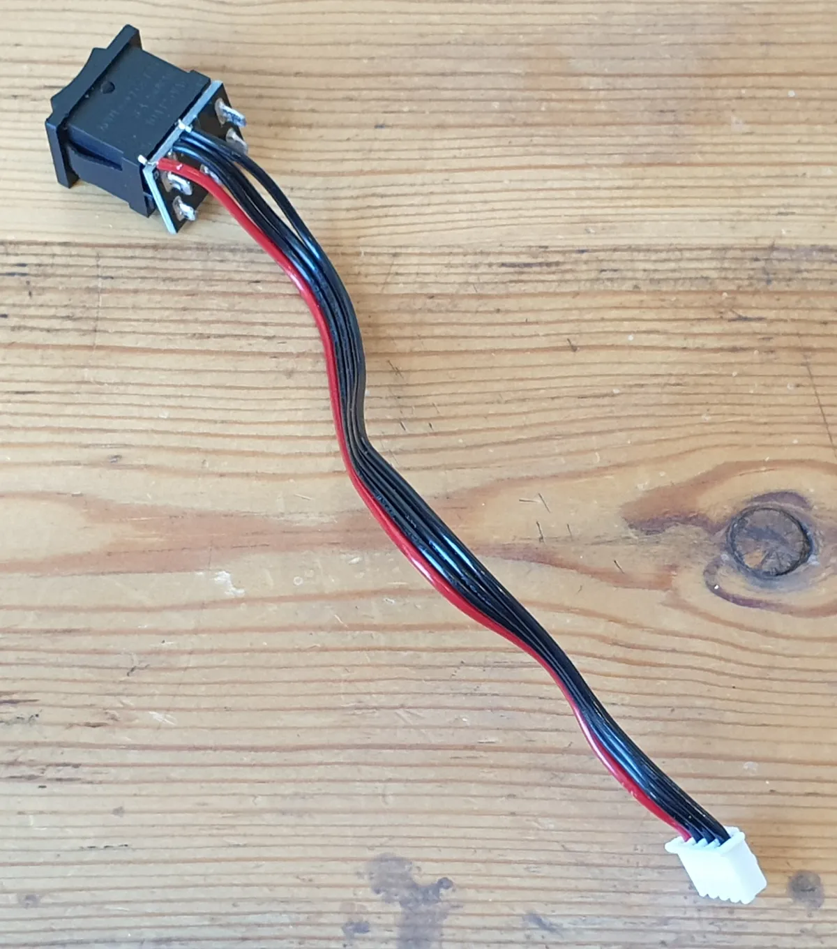 It comes with too much cable, and the PCB crudely soldered over the terminals is bigger than the ideal panel mounting hole. So that PCB needs to go.
Numbering the wires from black (1) to red (4), the pinout is:
| Wire | DPDT Pin(s) |
|---|---|
| 1 | 2 |
| 2 | 1 |
| 3 | 1b, 2a |
| 4 | 2b, 1a |
To remove the PCB I had to cut it apart in situ, then de-solder each terminal and slide off the corresponding piece slowly. Now directly wired, it looks like this:
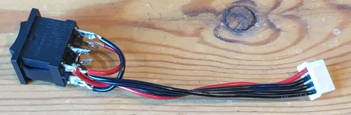 And despite my lacklustre soldering skills, it still works :)
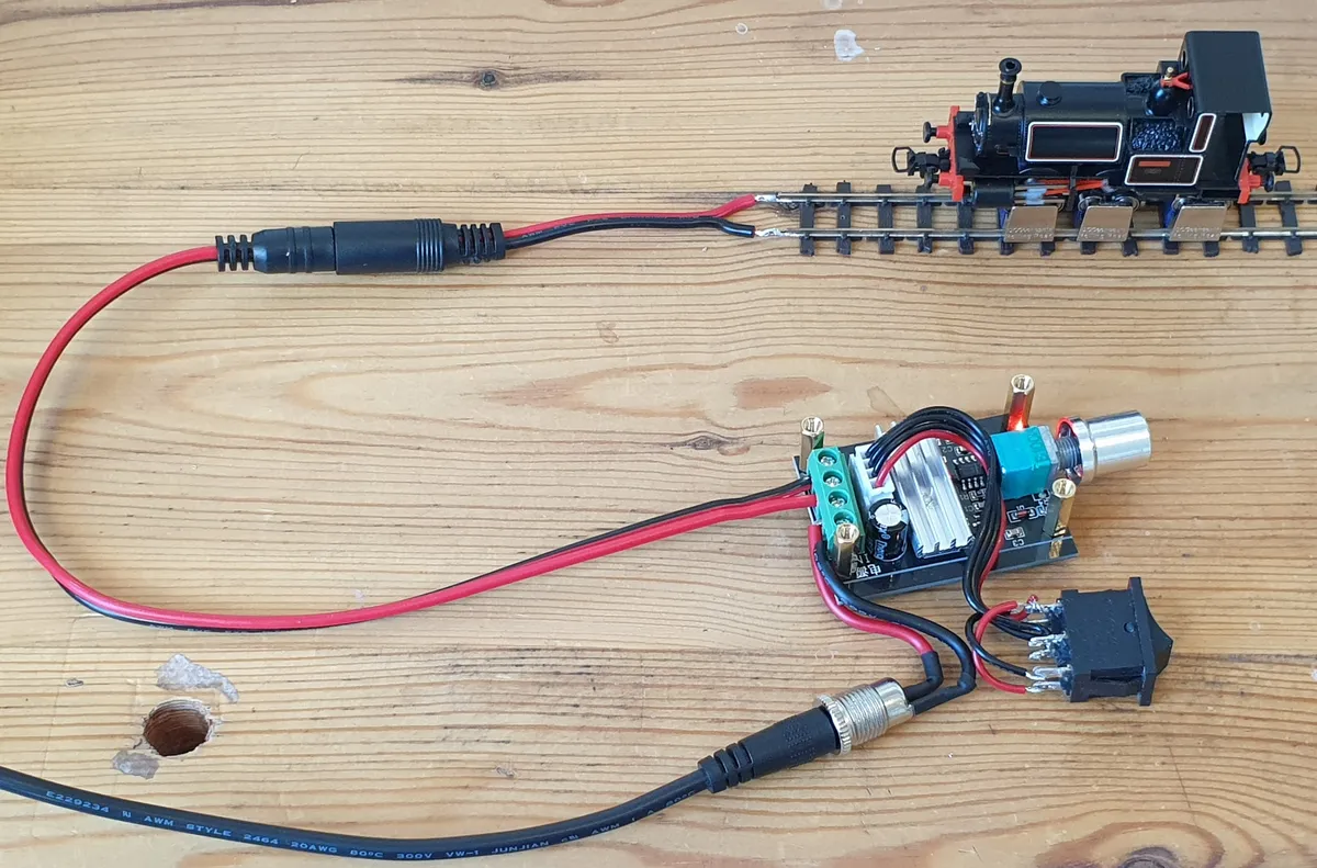
After replacing the power in with a 5.5x2.5mm socket, and connecting a tail cable with 5.5x2.1mm plug to the output, the final wiring is done. My use of two different DC plug sizes here is somewhat accidental, but it has the nice consequence that everything can only be connected the right way round. The PCB spacers (15mm) can be test fitted, and yes it still works:
A couple of lessons learnt:
- Don't be an idiot. 5.5x2.5mm and 5.5x2.1mm DC plugs and sockets are not compatible with each other.
- Just say no to TRS. The Default Bachmann Train Controller uses a 3.5mm TRS stereo jack for track power, with only the ring and sleeve connected. For a DIY controller, this design poses high risk of short circuit if the plug is inserted or removed while live. In theory this risk could be mitigated with a special socket, but I don't know if the Bachmann controller has this (I haven't tested it) and hacking a TRS socket just to gain compatibility with Bachmann track power cables is not worth the effort.
Making the Case
For some reason, I decided to use 2mm plasticard. This turned out to be suboptimal:
- Carefully sawing 2mm plasticard makes a lot of dust and takes ages.
- Scoring and snapping produces clean straight lines, but even with a sharp knife the scoring part still takes ages.
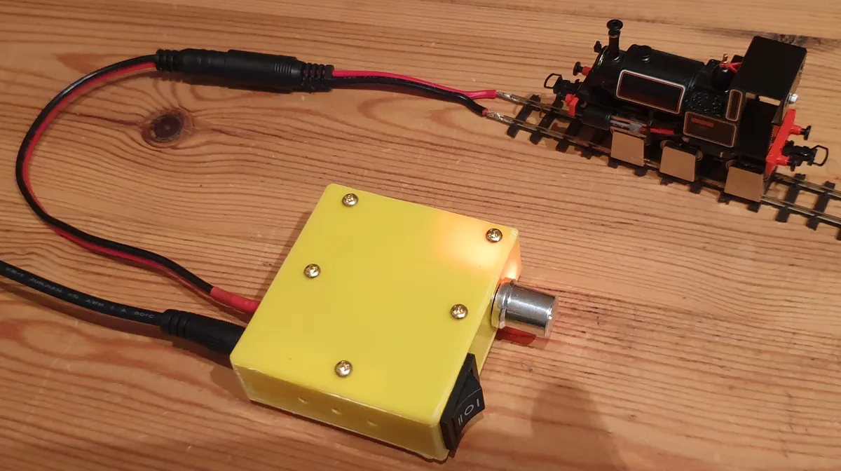
Nevertheless, some hours and an inordinate quantity of Revell Contacta later:
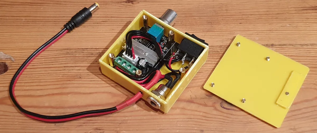
It still works, and it turns out there was no need to worry about the little indicator LED not being visible.
Yet more lessons learnt:
- Industrial design is hard. Especially in this case (pun intended):
- Assembly & disassembly. The lid is removable but because of the projecting potentiometer spindle I don't know whether the PCB could actually be removed through the opening!
- Ergonomics. I roughly chamfered the edges, but a smaller shape (reduced width) would be nicer to hold and use.
- Cable management. There must be a better solution for strain relief than a bit of heat shrink or a zip tie, but I don't know one.
- Making something of high quality (i.e. with good 'panel fit') by sticking pieces together is hard. I guess this is why most people use 3D printers or subtractive manufacturing for this sort of thing. Hmm.